This low real power (hence, low cost) consumption comes at the cost of of large reactive power consumption. This large reactive power demand may be easily ignored by user because they are not direct victim of this problem, but user as well as provider will suffer very much in the end.
Electricity providers only bill for real power, they do not collect money from user level for reactive power since, before the energy saving lamp, general user did not consume high reactive power. But they DO charge industrial customer at a different and higher rate than normal user because of consuming large reactive energy. That is why consumer and industrial feeder and bill rate are different.
The reason providers charge more for industrial application is higher reactive power consumption means
lower ability to provide real power and lower mean life for equipments.
 |
| Input |
 |
| Simulation circuit |
The input AC voltage is converted to DC by using a full bridge diode rectifier and is applied to a low pass filter. This circuit is equivalent to an ESL(provided that we are not describing or showing inverter section which produces high frequency AC). The input side inductance and resistance is due to the transmission line.
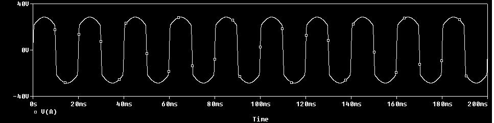
Output voltage is shown below.
 |
| Output |
 | |
| diode input |
 |
| Input and output |
This distortion in input voltage dictates the harmonics is created by filter action. Hence, harmonic current is also created and, if measured by an ammeter, shows more than expected RMS value. The reason is harmonic currents add to increase effective amount of current. This increased amounts of current flows through distribution transformer and cause more heating. If the excess amount of heat crosses the critical limit of temperature, temperature sensor stops transformer operation(Transformer trips). If many transformers begin to cease operation simultaneously, it will results in a catastrophic situation.
One important point that is important is exhibited by this demonstration. Energy saving lamp saves consumer energy and money, but results in increased system loss, reduced stability.
This problem can be solved by including an input filter in the circuit. A sample circuit and its input-output waveform is shown. Voltage magnitude is dependent on line parameters and is neglected here because the shape of wave form is more important consideration in case of harmonic distortion.

BPDB personnel said only low grade energy saving lamp causes this sort of problem, he claimed their lamps will not be LOW graded!!!
No comments:
Post a Comment
feel free to comment, I will be as responsive as possible. just don't spam.